Appliance Service TOOLS and INSTRUMENTS
| HOME | Troubleshooting | DIY Tips |
|
← → In addition to the commonly used mechanic’s hand tools, there are some specialized hand tools used by appliance technicians. The most popular of these tools will be covered at this time, followed by coverage of test instruments that are used in this field. TUBING CUTTERS Tubing cutters are used to cut tubing with a square end, enabling the appliance technician to make leak-tight connections. In practice, as shown in Fig. la, the cutter is placed around the tube. The cutter wheel is then tightened on the copper tubing, as shown in Fig. lb. Care should be taken not to tighten the cutter wheel too much because the tubing will be flattened and a leak-tight joint will be almost impossible to make. After the cutter wheel touches the tubing, the cutter handle should not be turned more than turn. See Fig. 2. Make a complete revolution of the tube with the cutter, then tighten the cutter handle no more than f turn again. Repeat this procedure until the tubing has been completely separated. To obtain a square end on the tubing, the tubing must be placed on the rollers so that the cutter wheel will be centered on the tube. 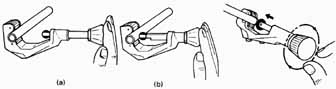 Fig. 1 Tubing cutter application. Fig. 2 Tubing cutter adjustment. (a) (b) Roller type with flare cut-off groove After the tubing has been completely separated, there will be a burr on the inside of the tubing. This burr must be removed or it will cause a restriction to the fluid flowing through it. Most tubing cutters have an attached reaming blade. See Fig. 4. This blade is rotated outward and then inserted into the tubing end. It’s then rotated to re move the burr. Care should be taken to prevent the loose metal chips from falling into the tubing where they will clog the strainers and filters, which will need to be removed for cleaning or replacement. Tubing cutters are also equipped with a flare cutoff groove in the rollers so that bad flares can be easily cut from the tubing. See Fig. 5. This permits easy removal of the flare with a minimum amount of wasted tube. It also prevents threading of the tube. 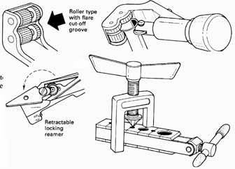 Fig. 3 Tubing cutter rollers. Fig. 4 Tubing cutter reaming blade. Fig. 5 Tubing cutter with flare-removing rollers. Fig. 6 Flaring tool. FLARING TOOLS Flaring tools are used to make a flare on the end of tubing so that flare fittings can be used to make leak-tight connections. See Fig. 6. When a flare is to be made, insert the tubing into the flare block so that approximately 1 inch extends above the flare block. See Fig. 7a. Swing the clamp into place against the end die and tighten it sufficiently to prevent slippage of the tube in the flare block. See Figure 3 Slide the yoke over the tubing and turn the feed screw 5 or 6 turns after the cone touches the tubing. See Fig. 7c. When the flare is completed, reverse the flaring process to remove the tube from the flaring block. Backing off of the cone automatically burnishes the flare to a highly polished finish. Flares made in this type of flaring block are stronger because the flare is made above the flaring block die, not against it, and the original wall thickness is maintained at the base of the flare. There is no chance of “washing out” the flare. Flaring tools can be used for re rounding and sizing bent tubing. TUBING REAMERS Tubing reamers are used to remove burrs from the inside of the tubing. See Fig. 8. After the tubing has been cut, the reamer is placed over the tube and rotated, removing the burrs from either the inside or the outside of the tube. Then the reamer is turned around and placed over the tube again and rotated to remove the burrs. Since these are multisized tools, one tool will fit many sizes of tubing. REVERSIBLE RATCHETS These ratchets are used to turn the stem on refrigeration service valves to allow service operations to be completed. The most common size is t inch. A 4inch square is pro vided on the end with a 4-inch six-point socket. There are a variety of sockets available to fit almost any size valve stem that will enable the technician to connect the refrigeration gauges to the system. Also available are a variety of packing- gland nut sockets that can be used with the reversible ratchet. These are used to tighten packing glands on certain valves to prevent leakage of refrigerant. GAUGE MANIFOLDS Probably the most often used tools in the service technician’s tool chest are the gauge manifolds. A gauge manifold is comprised of a compound gauge, a pressure gauge, and the valve manifold. See Fig. 9. All the service operations involving refrigerant, lubricating oil, and evacuation can be accomplished by use of this tool. Compound Gauges These gauges are used to read pressures both above and below atmospheric (vacuum). See Fig. 10. In practice, they are used to determine pressures in the low side of a refrigeration system. The outside scale is in pressure (psig). The inside scales are the corresponding temperatures for different refrigerants. Retractable locking reamer SECURE CLAMPING Sliding dies with lever clamping action TUBE HEIGHT GAUGE Slot in yoke is used for tube height gauge SLIP-ON YOKE Yoke slips over top of bar, then locks into position with slight turn 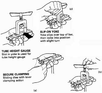 Fig. 7 Use of flaring tool. 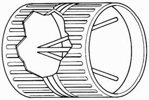 Fig. 8 Tubing reamer. Gauges operate due to the action of a Bourdon tube. See Fig. 11. When pressure inside the Bourdon tube is increased, the element tends to straighten. As the pressure is decreased, the element tends to curve again. A Bourdon tube is a flattened metal tube sealed at one end, curved, and soldered to the pressure fitting on the other end. The movement of the element will pull a link that is attached to the pointer through a series of gears. This movement will be shown by the gauge hand, or pointer. Compound retard gauges have a retarder that permits accurate readings within a given range. In refrigeration work this range would be between 0 and 100 psig. These gauges can be recognized by the change in graduations at pressures higher than those usually encountered. 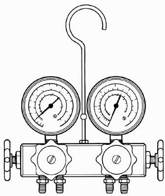 Fig. 9 Refrigeration gauge manifold. Pressure Gauges 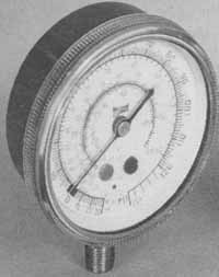 Fig. 10 Compound gauge. 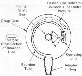 Fig. 11 Bourdon tube principles. 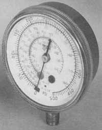 Fig. 12 Pressure gauge. Pressure gauges are used to determine pressures on the high side of the system. See Fig. 12. The outside scale is calibrated in psig, and the inside scales indicate the corresponding temperatures of the different types of refrigerants. Some pressure gauges are not designed to operate at pressures below atmospheric. Therefore, caution should be used during evacuation procedures to prevent damage to these gauges. Valve Manifolds These manifolds provide openings through which the various service operations are performed on the refrigeration system. See Fig. 13. The proper manipulation of the hand valves will permit almost any function. When the valves are screwed all the way in, the gauges will indicate the pressure on the corresponding line. The center line is usually connected to a vacuum pump, a refrigerant cylinder, or an oil container. Charging Hoses These hoses are flexible and are used to connect the gauge manifold to the system. See Fig. 1 Charging hoses are equipped with 1-inch flare connections on each end; some automotive units require a different size. One end usually has a valve core depressing attachment for attaching the gauges to Schrader valves. Charging hoses may be purchased in a variety of colors, which facilitate making connections to the unit and are designed for a working pressure of 500 psi and an average bursting pres sure of 2000 psi. POCKET THERMOMETERS An asset to the appliance service technician is the pocket thermometer. See Fig. 15. By using pocket thermometers much time can be saved. The operating temperatures of a unit can be checked upon completion of the service work to determine whether or not the unit is operating properly. The two types currently used are the mercury thermometer and the bimetal thermometer. The bimetal type is more popular because of its durability. Pocket thermometers can be purchased with a convenient shock-resistant carrying tube which can be clipped into the shirt pocket for ready use. Pocket thermometers are accurate to within 1 percent. CHARGING CYLINDERS These cylinders are used by the service technician to charge the correct amount of refrigerant into a system in a short period of time. In practice, the charging cylinder is loaded with the manufacturer’s recommended amount of refrigerant for a particular unit. See Fig. 16. While the system is under a vacuum, the complete refrigerant charge is dumped into it. Some of these units have a built-in electric heater to speed up the dumping process. These cylinders should never have a direct flame applied to them, nor should they be stored in direct sunlight or with liquid refrigerant in them. Pointer Shaft Gear Dashed Line Indicates Bourdon Tube Under Pressure Gauge Case Enlarged Cross-Section of Bourdon Tube Bourdon Tube Operating Link Adapter Fitting Special washer allows stem to close without turning no twisting or tearing seat Glass-impregnated Teflon* seat Stem moves in and out without turning Two full turns allow maximum flow 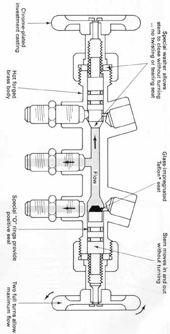 Fig. 13 Valve manifold FITTING BRUSHES Fitting brushes are used to clean the inside of fittings that are to be soldered. These brushes can be obtained for each fitting size. In practice, the brush fits tightly into the size fitting for which it has been designed. The brush is then rotated by hand to clean the fitting. If too large a brush is used or if it’s rotated in more than one direction, it will be ruined. MATERIALS Various materials are peculiar to the appliance industry. Because there are so many in use, we will cover those that are most commonly used. 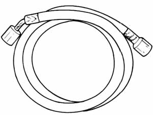 Fig. 14 Charging hose. 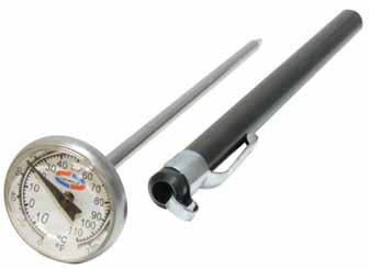 Fig. 15 Various types of thermometers. 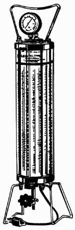 Fig. 16 Charging cylinder. Chrome-plated investment casting Hot forged brass body Special O-rings provide positive seal Silver Solder (Stay-Silv 15) This solder is the most common agent used in silver brazing joints in modern appliances. It’s sometimes referred to as silver brazing. It’s available in rods I X * x 20 inches, 0.050 x 20 inches, and 1, 3, 5, and 25 troy ounces and a inch in diameter. To silver-braze copper to steel or to braze dissimilar metals, the recommended product is Stay-Silv 45 alloy, which has a melting point of 1145°F. Also available are the Safety-Silv cadmium-free silver solders 1200 (56 percent silver), Safety-Silv 1370(45 percent silver), and Safety-Silv 1350 (40 percent silver). Their melting temperatures are according to their designated alloy number as listed. See Fig. 17. These solders have a strong tensile strength and are not affected by vibration. Some types of solder contain their own flux, eliminating the need for extra flux on the joint. This is especially true on copper tubing. Almost all alloys used today for brazing operations contain cadmium, a product that gives off poisonous fumes when heated. When using one of these alloys, make certain that there is plenty of ventilation, In modern times, however, there is no need to use an alloy that contains cadmium for normal silver-brazing operations. Most manufacturers make a cadmium-free silver-brazing alloy. It’s recommended that one of these be used when at all possible. Flux Flux is used when making sweat joints to aid in making leak-tight connections. It’s available in both paste and liquid forms. See Fig. 18. Caution: Flux has an acid content and should not be allowed on clothing, near the eyes, or on open cuts. To remove, wash the area with soap and water or see a physician. There is a flux designed specifically for each type of solder that cannot be used for another type of solder. Flux should be put on the joint sparingly. Don’t overflux a joint or allow flux to enter the piping system because the add will attack the internal components of the system. 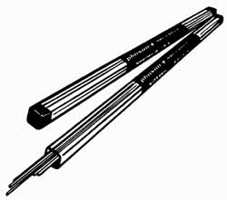 Fig. 17 Silver solder. 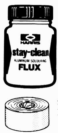 Fig. 18 Soldering flux.; Fig. 19 Sand cloth. Sand Cloth Sand cloth is mainly used to clean the surfaces to be soldered. It’s available in rolls at the supply house. See Fig. 19. Short strips are torn from the roll and wrapped around the tube. Each end is pulled alternately until the tube is shiny bright. Caution should be used when cleaning tubing to prevent the particles from entering the tube. Per haps the best way to accomplish this is to turn the end of the tube being cleaned downward so that the particles will fall away from it. TEST INSTRUMENTS Test instruments are valuable aids to the service technician. The use of test instruments seems to intimidate many service technicians, however, and they won’t make any effort to use these valuable tools of their trade. The use of test instruments is of great benefit to the customer as well as to the service technician. Test instruments should be just as familiar to the service technician as any other tool would be. Purpose Test instruments, when used, can help the service technician to perform service operations more accurately and faster, thereby providing a savings to the customer. There are two very strong arguments for the use of test instruments: first, the prevention of the unnecessary changing of parts that usually end up in the scrap box; second, the time saved is money. Customer satisfaction after the sale is not promoted by the parts-changing service tech., who costs the customer and the employer thousands of dollars each year in wasted parts and effort. 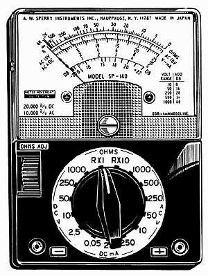 Fig. 20 Multimeter. Application--The proper application of test instruments will pro vide more accurate trouble diagnosis in the shortest possible time, providing a savings to the customer and effecting better customer relations. Multimeters--The multimeter is probably one of the most frequently used instruments. It’s also the easiest instrument to read. In practice, the selector switch should be set on the proper function for which the meter is to be used. When checking voltage and the correct voltage is not known, start checking the electrical circuit with the meter set on the highest scale possible and work down until one is found that provides a reading at approximately midscale. Midscale readings are the most accurate obtained. Ohmmeter The ohmmeter is used for measuring resistances, checking continuity, making quick checks on capacitors, and testing some solid-state components. See Fig. 21. Most ohmmeters are ruined because they are connected to a circuit or a component that has not been disconnected from the source voltage. Ohmmeters have their own power supply and cannot be safely used with any other power source. In practice, it’s better to start with the lowest resistance scale when an unknown resistance is to be checked. Then proceed through the higher ranges until the meter shows a midrange reading. This is the most accurate reading for a meter. Fig. 22 Wattmeter. When checking a resistance, first select the proper resistance scale. Install the probes in the proper jacks. Touch the ends of the probes together and turn the adjustment knob until the meter reads zero resistance while the ends of the probes are touching. If the scale is changed, the meter must again be calibrated to zero. If the meter cannot be calibrated to zero, the batteries should be replaced. When a switch or wire is to be tested for continuity, the needle should deflect to zero, indicating a closed circuit. The part being checked has continuity. If, on the other hand, the needle does not move from the at-rest position, the circuit is open. The part being tested does not have continuity. If the needle stops between infinity and zero, the meter is measuring the resistance of the part being tested. Infinity means that the resistance is extremely high; probably an open circuit is being tested. Ammeter--The clamp-on ammeter is the most popular current-measuring instrument used for ac circuits because the current flow can be checked without interruption of the electric circuit. All that is necessary to check the current flow is to clamp the meter tongs around one of the wires supplying electric power to the circuit being tested. Clamp-on ammeters are designed primarily to measure the current flow in ac circuits only. These instruments measure the current flow in a wire by making it serve as the primary side of a transformer. The circuit to the meter movement serves as the secondary side of the transformer. These instruments are most accurate when the current-carrying wire is in the center of the tongs. For best accuracy of the instrument, the mating surfaces of the tongs should be kept clean. When testing a circuit that has a low current flow, the wire can be wrapped around one tong of the ammeter. The sensitivity of the meter will be multiplied by the number of turns used. To obtain the correct amperage reading, divide the meter reading by the number of turns taken on the tong. Wattmeter--The wattmeter can be used to determine the voltage to the unit and the total wattage draw of the unit. Be sure to set the meter on the highest range possible because the starling wattage of most motors is very high. After the unit is running, the proper scale can be selected so that the needle indicates a midscale reading. Capacitor analyzer--The capacitor analyzer is a very important instrument to the service technician. It can be used to check for open or shorted capacitors, for the micro- farad capacity, and for the power factor. Scales are provided for both the voltage at which the instrument will be used and the microfarad rating of the capacitor. It may be used to check both running and starling capacitors. Temperature tester--Most electronic temperature testers have thermistor sensing leads that are used primarily to measure temperatures below 200°F. Don’t attempt to alter these leads in any way. If the leads don’t function properly, they should be replaced. By using these leads, temperatures at several different locations may be taken without interruption of the normal cycle of the unit. 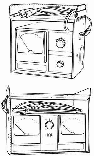 Fig. 21 Ohmmeter. 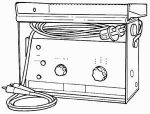 Fig. 23 Capacitor analyzer. The micron sensing element is not designed to mea sure above atmospheric pressure. Therefore, some means must be provided to protect the sensor when charging the system with refrigerant. Electronic leak detector Electronic leak detectors are very sensitive instruments. They operate by moving refrigerant vapor across an ionizing element. There are several ways to warn the user that a leak is present. Some instruments produce a high-pitched screech, some use a blinking light in the probe, and others use a buzzing noise. These instruments won’t function when either ammonia or sulfur dioxide is the refrigerant. QUIZ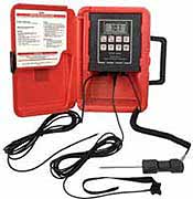 Fig. 24 Electronic temperature tester. Almost any number of leads can be used on instruments equipped with multiple connections. Temperature testers are also available that will record both the time and the temperature on a piece of paper. These instruments are valuable for helping to locate intermittent temperature-related problems. When this type of instrument is desired, be sure that the chart paper and inking supplies are available. Micron meter--When it’s desirable to have an accurate indication of the vacuum in a system, a micron meter the instrument most often used. These instruments are electrically powered and use a sensing probe to measure the thermal conductivity of the gases in the system being evacuated. These instruments are designed to measure the last part of an inch of vacuum and to indicate this measurement in microns. There are 25,400 microns in 1 inch. 1. What tool is used to cut a square end on tubing? 2. How far should the tubing cutter handle be turned after the cutter wheel touches the tubing? 3. After cutting the tubing what should be done to it? 4. What tool is used to make the fittings on tubing for leak tight connections? 5. What tool is used to remove burrs from the inside of tubing? 6. What tool is used to turn the stem on a refrigeration service valve? 7. What is probably the most used tool in the technician’s tool chest? 8. Name the two types of gauges used in refrigeration work. 9. What is the purpose of charging hoses? 10. What tool is used to charge the accurate amount of refrigerant into a system? 11. What type of solders have a strong tensile strength and are not affected by vibration? 12. Why should care be used when using soldering flux? 13. What devices can be used to aid the service technician when performing service operations? 14. What instrument is used to check resistances? 15. What is the most popular ac current measuring instrument? 16. On what scale should a meter be set when first measuring a circuit? 17. For what is a micron meter used? NEXT: Home top of page |