|
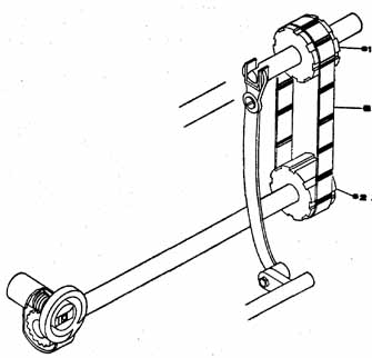
Sewing machines for home use can be broadly classified into two types: • Those that sew only a straight stitch. • Those that sew a zig-zag as well as a straight stitch. Insofar as internal mechanisms are concerned, these two basic types can be further classified in accordance with the type of loop-catching mechanism that's employed. Loop catching is a general term used to describe the interaction between the thread loop that's formed when the sewing machine needle carries the top thread through the material to be sewn, and the thread that's carried in the sewing machine bobbin. The two basic types can also be classified by the variations of stitching that can be produced by the machine. STRAIGHT-STITCH SEWING MACHINE The basic home-sewing machine, as it was generally (but not exclusively) known and used throughout the early part of this century and into the post World War II years, is the one that produces only a straight stitch. The top and bottom stitches are visible on the sewn material. Apart from an unwavering straight ness, this stitch has one characteristic in common with its zig-zag counterpart, inasmuch as in both types of stitching, the top and bottom stitches are interlocked between the two fabrics being sewn. The stitches are invisible, provided the machine is properly adjusted. Even when only one thickness of material is sewn (as in darning), the interlocking of the top and bottom stitches will virtually disappear into the fabric if the machine is properly adjusted. This interlocking feature, which is of primary importance to successful sewing, will be discussed in detail as we go along. The early straight-stitch machine was at once a marvel of ingenuity and simplicity for its time. Although it had only to sew a straight stitch, if the stitch was to be both durable and neat, the machine had to accomplish this with the top and bottom stitches firmly and invisibly interlocked. For the sake of appearance, the individual stitches had to be of uniform length and unwavering from the line along which they were sewn. Finally, to fulfill what was expected of mechanization, these machines were designed to operate at what would even today be considered reasonably high speeds. An early treadle-operated machine could be made to sew about 800 stitches per minute, and when this same machine was powered by a fractional horsepower electric motor, it would sew between 800 and 1,200 stitches per minute, depending upon the model. BASIC STRAIGHT-STITCH MECHANISMS It is by this time only of academic interest that the older sewing machines were powered by foot treadles, connected to an external driving mechanism by a series of linkages and pulleys which ultimately applied a rotating motion to the drive pulley of the machine as the foot treadle was pumped up and down. What is more important to understand is that, if the treadle mechanism was disconnected and replaced with an electric motor of the appropriate rating, RPM and pulley size (as was often done with the old treadle Singers), the rotating motion of the electric motor could be imparted directly to the drive pulley, via a reduction pulley and drive belt. The speed of the motor can be made variable by connecting a variable rheostat ahead of it in the electrical circuit. The rheostat can be made to operate as either a knee or foot control, thereby allowing the operator the freedom of her hands as she runs the machine through a range of speeds that's continuous between the lower and upper limits. The motors are typically rated on the order of around 1/20 horsepower, to be used universally on either alternating current, within a wide range of alternating current frequencies, or on direct current. However, the voltage rating of consumer machines manufactured for use in the U.S. is never in excess of the house-current voltage of 110-120 volts. The RPM of these small motors is generally around 4,000 to 5,000, which when imparted to the drive pulley at a reduction of about 7:1, will cause the machine to operate throughout an optimum range of speeds when activated through the rheostat control. Depending upon the manufacturer, some motors are equipped with oiling points through which the bearings can be oiled. Others require no oiling throughout their lives. Motor maintenance, which consists primarily of replacing brushes, will be discussed in more detail in Section 3. If a motor is allowed to run free, that's , disconnected from the belt that couples it to the drive pulley of the machine, it may be damaged. The rotating motion of the drive pulley is transmitted to the various internal mechanisms, and thence to the external sewing mechanisms, through a series of shafts, cranks, connecting rods, linkages, gears, pulley, belts and eccentrics. Moreover, since the motions of the mechanisms in the upper arm of the machine (the reciprocating motions of the needle bar and take-up lever) must synchronize with the motions of the mechanism in the lower bed of the machine (the feed dog and the loop-catching mechanism), these upper and lower internal mechanisms must be connected together. As a general statement, we can say that if the sewing machine is of an older vintage, with the old-style, vibrating loop-catching mechanism, or a more recent but less expensive model with the oscillating loop-catching mechanism, the upper and lower internal mechanisms will be connected together by a connecting rod, forked to fit a crank bend in the main (upper) shaft and thence to a pivot point on the shuttle driving (bottom) shaft. This arrangement transmits a vibrating or oscillating motion to the loop-catching mechanism. If, on the other hand, the machine is the new, or more expensive, model with a fully rotating loop-catching mechanism, the upper and lower mechanisms will be connected together with either a timing belt or a shaft geared to the main shaft, thereby creating a more positive, full rotation of the loop-catching mechanism. In either arrangement, however, the back-and-forth motion of the feed dog will usually be accomplished through a forked feed drive connection that's fitted to a cam in the main shaft in the upper mechanism and to a pivot point on the feed drive shaft in the lower mechanism. To better understand the basic mechanism, refer to Fig. 1-1.
As the main shaft (S) rotates, cam (c) rotates, imparting a rocking motion to the forked feed drive connection (F) which is transmitted through the feed drive shaft (SD to the feed dog (D). Simultaneously, the crank bend (b) imparts an oscillating motion to the connecting rod (R), which transmits that motion laterally through the shuttle connecting shaft (Ss) to the bobbin shuttle (B). Each lime the main shaft makes one complete revolution, the bobbin shuttle makes one oscillating motion that places the shuttle hook in position to pick up a thread loop, and a second oscillating motion that moves the hook about 180-degree from the loop pick-up position, where the looped thread will slip off the hook and pull the bobbin thread up into the material. Further, with each complete revolution of the main shaft, the needle bar (N) goes through one complete cycle, and the take-up lever (T) also goes through one complete cycle. The functions of the needle bar, take-up lever and shuttle will be explained more fully under the heading Loop Catching Mechanisms. It is also necessary that as the feed dog is made to go back and forth by the feed drive mechanism, it must also be made to move up and down. This will be explained more fully under the heading Feed Drive Mechanism. This up and down motion can be accomplished in a variety of ways, and in this particular mechanism, as the oscillating shuttle spindle (SS) oscillates, the roller (r1) rides up and down on a spiraling shoulder that's incorporated into the shuttle spindle, imparting a similar up-and-down motion to the fork (Fd), which is transmitted through roller (r2) to the feed dog.
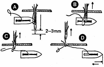
Moreover, since accurate synchronization, or timing, of the upper and lower mechanisms is essential, the relative positions of these upper and lower mechanisms are established through the design and installation of the parts. If the upper and lower mechanisms are connected through rods (as in Fig. 1-1), this timing is established by simply installing the main shaft, connecting rods and lower shafts so that when the crank bends of the main shaft are imparting maximum thrust to the forked rods, the lower shafts are at their maximum throw. If the upper and lower mechanisms are connected through a combination of connecting rod and timing belt (Fig. 1-2) the timing of the upper mechanism to the feed dog is accomplished as described above and the timing of the upper mechanism and the rotating shuttle is accomplished through the relative positions of the sprockets (s1) and (s2). They are maintained by the cleated timing belt (B). In this latter arrangement, the repairman is aided in the installation of major parts by timing marks, the locations of which will be described in the Sections relating to specific brands and models. Once the basic timing of the mechanisms is established through the correct installation of the major parts, precision timing of the shuttle, feed dogs, needle bar, etc., is accomplished through adjustments at these points, which will be described in detail in Sections 3 and 7. Loop-Catching Mechanism As indicated earlier, loop catching is a general term to describe the interaction that takes place between the thread loop that's formed when the sewing machine needle carries the top thread through the material, and the bottom thread that's supplied by the sewing machine bobbin. The sewing machine needle has a long groove on one side and a short groove on the other side, the purpose of which is to provide a space for the thread, thereby minimizing resistance as the downward cycle of the needle pushes the thread through the material. When the needle has reached its lowest point, the thread on both sides of the needle is pushed firmly into the grooves. Simultaneously, the take-up lever is moving downward in its cycle, supplying thread. When the needle rises just slightly (2mm to 3mm in most machines), the thread on the short grooved side of the needle jams against the body of the needle, causing a loop to be formed. The take-up lever continues to move downward, supplying thread so that the loop can be enlarged. It is then that the timed action of the shuttle causes the bobbin and bobbin thread to be passed through the loop, in the case of the vibrating shuttle (Fig. 1-3), or the loop to be carried around the bobbin, and thus around the bobbin thread, in the case of the oscillating shuttle or the rotating shuttle (Figs. 1-4 and 1-5).
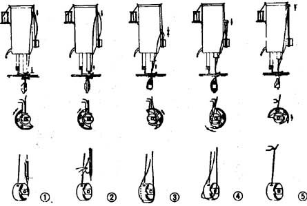
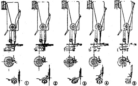
Regardless of which shuttle is used, the end result is that the top and bottom threads are now interlocked. The take-up lever continues to move downward until the needle is about halfway up and out of the material. It then starts its upward motion to tighten and firmly interlock the stitch by pulling against the tension created between the upper tension regulator and the bobbin tensioner. The needle is raised to its highest point and starts downward. At about the same instant, the take-up lever begins its downward motion, and the cycle is repeated. In case there is no material for the needle to penetrate, a slack loop will nevertheless be formed when the needle is passed into the shuttle area on a downward cycle. This loop will fulfill effectively the same purpose as the loop just described, allowing the operator to pick up the bobbin thread in preparation for sewing. As suggested above, there are three kinds of shuttles in general usage today: • the vibrating shuttle • the oscillating shuttle • the rotating shuttle When shopping for a used sewing machine, you should ask the dealer to tell you which kind of shuttle is used in the particular machine that interests you. If it's a vibrating shuttle you can assume that in age, this machine pre-dates one that has either the oscillating r rotating shuttle. If it has an oscillating shuttle, you have to determine the age of the machine from other factors, since oscillating shuttle machines are still being manufactured. In judging the value of machines of comparable age, you can assume that if all other factors seem equal, the rotating shuttle machine is considered superior to the oscillating shuttle machine. Accordingly, if you are comparing the costs of new machines, you will find that in a given brand of machine, top line machines have the rotating shuttle, while the less expensive models have the oscillating shuttles. The exception to this general rule is that as the trend in new machines is more and more toward the more efficient rotating shuttle, sacrifices in convenience features are made in the less expensive models. Descriptions and working methods of the three shuttle systems are as follows: The Vibrating Shuttle. The vibrating shuttle (Fig. 1-3) may also be called the boat shuttle. It is a torpedo-shaped shuttle which holds a long, cylindrical bobbin. The vibrating action of this shuttle, which is along its axis, is timed so that the shuttle will pass through the top thread loop, thus passing the bobbin thread through the loop. Note that it doesn't begin its return motion until after the needle has passed through the material on its upward stroke. The Oscillating Shuttle. The oscillating shuttle (Fig. 1-4), which is semi-circular in shape, partially encircles the bobbin holder. It is designed with a pointed portion, called the hook, which passes through the loop as shown in Fig. 1-4. • Step 1 shows the needle at its lowest point, with the take-up lever having passed its highest point and moving downward. • Step 2 shows the clockwise oscillation of the shuttle to where the hook enters the loop • Step 3 shows the hook carrying the loop around the bobbin thread as the shuttle continues its clockwise motion, with the take-up lever at its lowest position and ready to be raised. • Step 4 shows the hook about 180-degree from where it picked up the loop. The upward motion of the take-up lever pulls the loop off the hook. • Step 5 shows the top and bottom threads interlocked, the take-up lever at its highest point and the shuttle moving counterclockwise to return to its starting position and re peat the cycle. The Rotary Shuttle. The rotary, or fully rotating shuttle (Fig. 1-5) is also equipped with a hook that passes through the loop.
• Step 1 shows the needle at its lowest point with the take-up lever moving downward and the shuttle moving clockwise. • Step 2 shows the take-up lever continuing to move down ward and the hook entering the loop. • Step 3 shows the take-up lever at its lowest point, the needle being raised above the material and the loop being carried around the bobbin thread. • Step 4 shows the take-up lever being raised and the thread loosely interlocked. The hook has returned to its original position, where it will not pick up a loop this time because the needle is above the material. • Step 5 shows the take-up lever in its highest position and the threads firmly interlocked. The needle is descending and the timed action of the shuttle is carrying the hook clockwise to where it will pick up a loop and the cycle will be repeated.
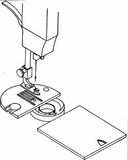
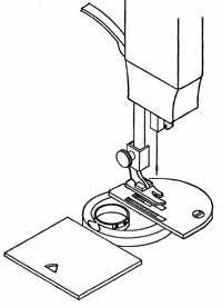
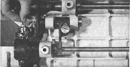
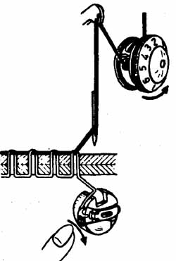
Identifying the Shuttle To identify the shuttle used on a particular machine, you may gain access to the shuttle by one of a variety of methods, depending upon the machine: • By rotating the balance wheel slightly toward you, make sure the needle is at its highest position. • If the throat plate is the divided type that can slide toward you or to the left (Figs. 1-6 and 1-7), slide it and the shuttle mechanism and the bobbin will be exposed. Remove the top thread and with the presser foot in the up position, rotate the balance wheel toward you. 1. If a torpedo-shaped shuttle moves laterally across the area of the bobbin, the machine is of the vibrating shuttle type. 2. If a circular shuttle oscillates back and forth around the bobbin, the machine is of the oscillating shuttle type. 3. If a circular shuttle rotates completely around the bobbin, the machine is of the rotating shuttle type. • If the throat plate is of solid construction, or doesn't slide, you can assume that access to the bobbin and shuttle must be gained underneath the bed of the machine. This is done either by swinging the head of the machine up and back or as done primarily on portables, by opening access doors at either the front, or the left end, of the machine. Since the bobbins in this type of mechanism are installed vertically, with their rotating axes parallel to the bed of the machine, they must first be installed in the bobbin case and then in the machine, with the hole of the bobbin over a centrally- located stud. The bobbin holder will be equipped with a latch, which serves the purpose of retaining the bobbin case and bobbin in the shuttle (Fig. 1-8). To remove the bobbin case and bobbin, spring the latch outward and pull the bobbin case out of the mechanism. To determine whether this machine has the oscillating or rotating shuttle (it will not have the vibrating shuttle), go through the procedures 2 and 3 just described, being sure to remove the top thread and raise the presser foot before rotating the balance wheel. To re-install the bobbin case and bobbin, be sure the needle is again at its highest point. Then with the bobbin in the case, and the thread threaded through the bobbin tensioner, place the entire assembly over the central stud and rotate it slightly to left or right while pushing. It will snap into place with an audible click. When the bobbin case is firmly in place, you should not be able to remove it without Springing the latch outward.
If the machine is of the oscillating or rotating shuttle type, it's called a central-bobbin machine (because the bobbin is centrally located in the shuttle mechanism). If access is gained to the bobbin through the top of the machine, it's called a drop-in or top-loading machine. If access is gained under the bed of the machine, it's called a front-load machine (in which case the side of the bobbin faces the operator), or a side-load machine (in which case the side of the bobbin faces the left end of the machine). In the drop-in machine, the bobbin case is an integral but removable part of the machine, and the thread-loaded bobbin is simply dropped into the bobbin case. In the side-load or front-load machine, the thread-loaded bobbin must first be placed in the bobbin case, and then into the machine as just described. In either type of machine, the bobbin case itself must be threaded with the bobbin thread before the machine will sew. More details on threading the bobbin case will be given in Section 2. The Tensioning Mechanism Earlier in this section, we said that the interlocking of the top thread the bobbin thread in such a manner that the interlocked portion of this stitch was drawn up into the material was of primary importance if the finished stitch was to be both durable and neat. The correct interlocking of the stitch is accomplished through the tensioning mechanism, which consists of • a tension regulator for the top thread • the take-up lever • the bobbin tension spring (Figs. 1-9 through 1-11). Table 1-1 determines the causes, reasons and remedies of various occurrences of interlocking stitches for these three illustrations. The Tension Regulator. The tension regulator (Fig. 1-9) is mounted on the front of the machine head and easily accessible to the operator since changing of the top thread tension is necessary if correct stitching is to be maintained throughout a variety of threads and materials. The top thread from the spool is invariably threaded into the tension regulator before it's threaded through the take-up lever, thus creating a point of tension between the take-up lever and thread source. To eliminate the guess work from upper thread tensioning, the tension regulator is equipped with a calibrated dial. Higher numbers (or + divisions) represent higher tensions than lower numbers (or - divisions). Regardless of the tension of the top thread, it will be released when the presser foot is up. There are no parts in the upper tension regulator that move in conjunction with the machine mechanisms.
Take-up Lever. As the take-up lever (Fig. 1-10) moves up and down through its cycles, it performs two basic functions:
The Bobbin Tensioner. The bobbin case is equipped with a spring and regulator screw so that the bobbin thread can also be fed under tension (Fig. 1-11). Without this tension, the pull of the upper thread as the take-up lever rises would pull the thread completely through the material, and thereby form loosely interlocked loops with the interlocking appearing on the top surface of the material. The bobbin case has no parts that move in conjunction with the running machine.
In troubleshooting the causes of faulty interlocking stitches, it's important to understand the interplay between the upper tension regulator and the bobbin case. You should also understand that with no moving parts in either the upper tension regulator or bobbin case, there is little likelihood that mechanical problems will arise in the tensioning system. Accordingly, most tensioning problems are corrected through operator adjustments. However, there are times—such as in the disassembling, cleaning and reassembling of the upper tension regulator—when knowledge of repair techniques is necessary to keep this system in working order. More details on adjusting and maintaining the tensioning system will be given in Sections 2 and 3. The Feed Mechanism In sewing, material is automatically fed through the machine at a uniform rate, with no more than minor manipulation by the operator to guide the material. This is accomplished with a set of feed dogs, activated by the rocker arm that's connected to the feed-driving connection (refer back to Fig. 1-1). In normal sewing, the cycle of the feed dog is as follows: At the instant that the needle is just rising out of the material on its upward stroke, the top surface of the feed dog is below the needle plate. As the needle rises clear of the material, a vertical lift is applied to the feed dog in order that the top surface of the feed dog will come in contact with the material, and simultaneously, a horizontal motion will be imparted to the feed dog in order that the material will be moved either forward or backward while the needle is out of the material. As the needle goes through its cycle and again enters the material, the feed dog is lowered below the surface of the needle plate, and simultaneously, no horizontal motion is imparted to the feed dog. The sum total of this motion is that the feed dog rises, contacts the lower surface of the material and moves horizontally while the needle is out of the material and lowers while the needle is in the material. For extraordinary sewing applications, such as darning, sewing on buttons or embroidering, when it's not desirable to have the feed dog come in contact with the material, most machines have a provision for lowering the feed dog and disengaging the feed mechanism. This is called a drop feed. The Needle Reciprocating Mechanism The needle reciprocating mechanism consists of a needle bar and the linkage that connects it to the cam on the end of the main drive shaft (again refer to Fig. 1-1). The lower end of the needle bar is equipped to insert a needle (or optionally a double needle in certain models), and since the needle dimensions and characteristics are of crucial importance to successful sewing, the needle can rightfully be considered a part of the needle reciprocating mechanism. The proper selection and use of needle will be discussed in detail in Section 2. Referring again to Fig. 1-1, you can see that the needle will go through one complete cycle with every revolution of the balance wheel-and-main shaft. The needle bar connecting linkages and the characteristics of the mechanisms that transmit motions to the oscillating or rotating shuttle causes the needle bar to go through one complete cycle while the oscillating shuttle goes through one oscillation cycle, or the rotating shuttle goes through two complete revolutions. In either type of shuttle, the area of the needle between the point and the eye (where the loop is formed) must be opposite the shuttle hook, yet close enough that the hook can pick up a loop, each time the needle has reached its lowest position and risen about 2mm (on most models). In fact, the correct juxtaposition of the needle and the shuttle hook is so important at this instant of the sewing cycle that a needle of incorrect length, or one that's incorrectly installed, can create sewing problems. Apart from the needle considerations, timing problems between the shuttle hook and needle are usually corrected by adjusting the needle bar height or by adjusting the shuttle hook. These adjustments, which are internal adjustments normally made by a repairman, will be discussed in detail in Section 3. Table 1-1. Interlocking Stitches Occurrences.
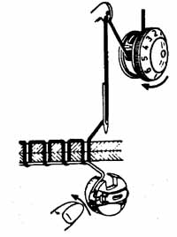
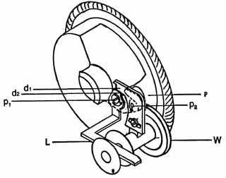
The Bobbin Winding Mechanism Virtually all sewing machines have a provision for winding thread on the bobbins by using some part of the basic sewing mechanism. Except on a few recent models, this is accomplished by installing the empty bobbin on a bobbin winding mechanism that can be engaged with the main drive pulley, then inserting the end of the thread that's led from the thread source to the spool and running the machine. Referring to Fig. 1-12, bobbin winding is accomplished by placing the empty bobbin on the bobbin winder spindle, threading the thread through the small hole of the empty bobbin, and depressing, the lever (L) downward into the empty bobbin. This places dogs (dl) and (d2) in the positions shown, with a spring tension at pivots points (p1 and p2), and the bobbin winding drive wheel (W) against the outer circumference of the main driving pulley (P). When the bobbin is fully wound the thread forces the lever upward, causing (dl) to pivot and allowing dog (d2) to be released. The tension at pivot point (p2) then kicks the bobbin winding wheel away from the main pulley.
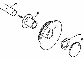
Main Drive Pulley Disengaging Mechanism So that the internal mechanisms of the machine will not move while the main drive pulley is turning against the bobbin winding wheel, a provision is made to disengage the main drive pulley from the main shaft. Referring to Fig. 1-13, when the parts are fully assembled for normal operation, the clutch (C) is pinned to the main shaft (5). When the central hub (H) of the main drive pulley slides over the clutch in assembly, the notched end of the clutch extends slightly past the end of the central hub. The clutch washer (W) is installed so that its body presses flush against the central hub and the flanges of the washer fit into the notches of the clutch. When the knurled hand-knob (K) is screwed snugly into the clutch, the washer is pressed snugly against the central hub, thus engaging the main drive pulley with the main shaft. Conversely, when the knob is loosened, the pressure on the washer is reduced, allowing the main drive pulley to turn freely around the clutch. The small screw in the knob simply extends past the knob far enough that when the knob is turned counterclockwise (to loosen), the screw strikes one of the ears on the washer. This prevents the operator from inadvertently backing the knob out so far as to let the washer flanges slip out of their notches.
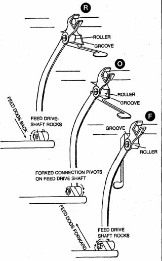
STITCH VARIATION OF THE STRAIGHT-STITCH MACHINE The only stitch variation on extremely old straight-stitch machines is a variation in stitch length. On models developed within the past 30 or 40 years, it's possible to vary the length of the stitches, and also to reverse the direction of stitching. Since most normal sewing jobs don't call for extensive reverse sewing, this latter feature is simple a convenience feature that keeps the operator from having to turn the material when sewing in reverse to lock the end of a stitch or reinforce stitch stress points. The stitch length regulating mechanism allows the operator to vary the length of the individual stitches when sewing forward from zero stitches per inch to about six or seven stitches per inch. Stitch lengths are calibrated in millimeters on recent models, with 1mm approximating 25 stitches per inch. Stitch length regulation when sewing in reverse is also variable, but not as accurately as when sewing forward. All the stitch length variations are continuous within the given range. The following is how the basic stitch regulation mechanism works (Fig. 1-14).
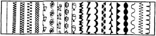
A three-pointed cam, which is incorporated into the main drive shaft, imparts a rocking motion to the forked connection. A roller on the side of the forked connection is fitted to ride in a groove of the stitch regulator lever, which can be moved up or down at the operator’s will. Assuming the three positions (F, 0 and R) in Fig. 1-14 represent one position of the three-point cam (the machine not in motion): • Illustration F shows the groove tipped so as to cause the forked connection to rock the feed mechanism rocker shaft clockwise (viewing the mechanisms from the right end), thereby pushing the feed dog to an extreme forward position. If the machine is started with the mechanisms in the position shown, the synchronization of the various mechanisms will cause the feed dog to be lowered as it's reversed, and raised on the next forward thrust. This causes the material to be moved forward in the sewing operation. • Illustration R shows that if the stitch regulator lever is moved upward, the feed mechanism rocker shaft will be rocked counterclockwise, thereby moving the feed dog to its extreme back position. This effectively reverses the cycle of the feed mechanism as it works in synchronization with the lowering and raising of the feed dog. If the machine is started with the mechanisms in the positions shown, the synchronization of the various mechanisms will cause the feed dog to be lowered (just as in the first case) while the feed dog moves forward; and raised as it moves back ward, thereby causing the material to be moved backward in the sewing operation. • In Illustration 0, which shows the groove to be on a minimal incline, the roller can ride along the groove without imparting any rocking motion to the feed mechanism rocker shaft. In this position, the forked connection simply pivots in its rocker shaft pivotal point, and the stitch length is minimal, or zero inches. Stitch length variation and reversal may be accomplished somewhat differently in different machine brands and models, but as a general statement, it can be said that these variations usually originate from a feed driving eccentric imparting a rocking motion, which can be variable, to the feed mechanism rocker shaft. This works in synchronization with the raising and lowering of the feed dog. In most machines, the accuracy of the stitch regulation is maximum when the lever is set at a normal stitch length, and may diminish slightly as the stitch length approaches zero and goes into reverse. ZIG-ZAG STITCH SEWING MACHINE The zig-zag sewing machine, which became widely available and quite popular in the 1950’s, has by now almost preempted the straight stitch machine (a few straight stitch machines are still being manufactured, however) because of the variety of decorative and functional stitching it can produce. In addition to zig-zag stitching, it will perform every function of the straight stitch machine. The zig-zag stitching of the earlier zigzag machines was more functional than decorative, but as a larger variety of zig-zag patterns has been provided through a larger variety of cams, decorative stitching is a large part of the appeal of zig-zag machines. At the same time, the functional importance of zig-zag stitching has in creased with the advent of stretch materials and polyester threads. Functionally, the zig-zag stitch adds strength to stitched seams by providing an accordion-like effect to stitching that keeps the stitch from breaking when stress points (or certain fabrics) are stretched; provides a relatively simple means of darning or inserting patches in which the patch and original material are butted together; and provides a relatively simple means of sewing on buttons or sewing buttonholes without special attachments. Decoratively, variations of the zig-zag stitch can produce many styles of decorative stitching (Fig. 1-15) as well as a variety of embroidery patterns. Experienced operators can embroider names and pictures on fabrics quite quickly by using certain techniques with the built-in or supplemental zig-zag cams.
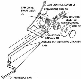
BASIC ZIG-ZAG STITCH MECHANISM A zig-zag sewing machine employs all of the mechanisms of comparable straight-stitch machines including the feed driving mechanism, bobbin shuttle mechanism, etc., since the sequence of forming a thread loop and catching it with the shuttle hook remains essentially the same in the zig-zag as in the straight-stitch machine. The primary difference between the two mechanisms is that the needle bar of the zig-zag machine can be made to swing from side to side for a controlled distance while the feed dog is feeding the fabric. The stitch length regulator can be set any place on the calibrated dial to produce a longitudinal distance between the apex points of the zig-zag stitches that's the equivalent of a stitch length. Thus, instead of a line of stitching in which the individual stitches are lined up like the links of a stretched chain, the basic zig-zag stitch will zig-zag from side to side while it proceeds along the line of sewing. To understand the zig-zag mechanism, refer to Fig. 1-16. A worm gear on the main shaft is geared to the cam drive shaft (Gc) so that as the main shaft makes one revolution, the cam driving shaft will make about 15 revolutions. If a cam (c1) is installed on this shaft, each time a high spot on the cam contacts the point of the lever (L1, for example), the lever will rock. This rocking motion will be transmitted through connecting linkage (1c) to the needle bar as a similar rocking motion with the frequency of the motion—and thus the pattern of the stitch—depending upon the contour of the cam. Levers (L1 and L2) pivot independently so that the supplemental cam (C2) can be made to replace the permanent cam (C1) by simply disengaging and engaging the appropriate levers.
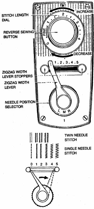
On a theoretical or basic zig-zag mechanism, a cam to produce a zig-zag stitch of optimum design is installed as a permanent part of the mechanism, with the needle bar throw lever extended to an external control lever through which the operator can place the lever in contact with the cam at will. In such a case the machine could be made to sew a straight stitch by moving the point of the lever away from the contour of the cam or to sew a zig-zag stitch by moving the point of the lever into contact with the contour of the cam. To give such a system more variety, a variety of cams to produce a variety of styles of zig-zag stitches could be installed on this shaft, with a separate, independently pivoting lever for each cam. In this system the operator would have the options of sewing a straight stitch by leaving all the levers away from the contours of their respective cams, or sewing the zig-zag stitch with a design of choice by placing the appropriate lever in contact with its cam contour. This system can be made even more flexible and comprehensive by extending the cam shaft to some convenient, external part of the sewing machine, as in Fig. 1-16 where the operator can install supplemental cams that are supplied by the machine manufacturer? One of the above methods of changing zig-zag stitch designs, or some variation of it, is used in all the zig-zag machines in use today. For example, if the cam shaft is brought to some external location, the internal cams may be entirely eliminated (as they might in an economy model), or they may be included to provide a few basic zig-zag designs with the variety extended by externally installed supplemental cams. In most economy models, all the cams are operator-installed, externally. In older top-line models the cams may be internal, contacted through external levers—or a combination of internal cams and the option of using supplemental cams on an external shaft. On the more recent top-line models, all the cams are internal, and the control levers have given way to control panels, through which the operator can contact the cam design of her choice by activating electric relays. Zig-Zag Stitch Width Regulation The width of the zig-zag stitch is adjustable, from about 0 (straight stitch) to about 5mm, through an external dial or lever (Fig. 1-17). The mechanism for making this change may be one that places the cam lever where it will not ride into the lowest contour of the cam, thereby limiting the distance of travel of the lever, or by any one of several different other methods, depending upon the brand and model of the machine. It is usually quite easy to gain a visual access to this mechanism by removing the top cover of the upper arm of the machine. On some models, further visual access can be gamed by removing a plate on either the front or rear of the upper arm of the machine.
Needle Position Zig-zag machines have a provision by which the operator can change the needle position (Fig. 1-17) from the extreme left of the central position of the needle arm swing, to the central position, to the extreme right position. When straight stitching, the machine will sew at the extreme left when the needle is set at the left, along the center when the needle is set at the center, etc. Further, this regulation can be used when zig-zag stitching, to sew a zig-zag pattern to the left, center or right of the center line, provided the stitch width is no more than about 2½ mm or one-hall the widest setting of the stitch width dial. This needle position regulating mechanism is connected to the needle bar through linkages, and it's also easily accessible for a visual examination on most machines. STITCH VARIATIONS OF THE ZIG-ZAG MACHINE The number and style of stitch variations possible on the zig-zag machine is a corollary of the cams that are built into the particular machine. If a provision is made for external cams, it also depends upon the number and style of supplemental cams that are available from the manufacturer. As explained earlier, as the point of the lever follows the contour of the lever follows the contour of the cam, the information that's programmed into the cam will be transmitted from the lever-point to a connecting linkage and thus to the needle bar, where it will be interpreted as a right-left needle bar swing. From the viewpoint of troubleshooting a zig-zag system, it's helpful to understand that the contour of the cams regulate the frequency of the needle bar swing, but the amplitude of the swing is determined by the cam contour working in conjunction with the stitch width regulator. Therefore, if correctly adjusted stitch width regulator is set at 0, there will be no needle bar swing even though a lever point contacts a cam. Further, if optimum results are to be obtained from a zig-zag system, it's essential that the setting of the stitch width (0 to 5mm); needle position (left, center or right); stitch length; and cam selection be made in accordance with instructions provided with the machine. SUMMARY The information in this section has been presented to give you a grounding in basic sewing machine mechanisms. Although the explanations and illustrations were developed from actual sewing machines, we have made no attempt to relate them to specific manufacturers’ brands or models. The fortunate fact is that through the years most of the changes in sewing machines have come through the addition of convenience features, but there have been extremely few radical departures in basic mechanisms. Therefore, the following general rules will apply, regardless of the brand or model of the sewing machine: • When the main drive shaft makes one revolution corresponding to one revolution of the balance wheel: — The take-up lever will go through one complete cycle. — The needle bar, and thus the needle, will go through one complete cycle. — An oscillating shuttle will go through one complete cycle, causing the shuttle hook to be in position to pick up a thread loop the instant one is formed. — A rotating shuttle will make two complete revolutions (this is determined by the relationship between the gears of the shuttle shaft and the shuttle driving shaft), with the shuttle hook picking up a thread loop every second revolution. — The feed dog will go through one complete cycle, pro vided that the stitch length regulator is set on a number other than 0. • Regardless of whether the feed dog is programmed to feed fabric forward or backward, the top surface of the feed dog teeth will be below the throat plate when the needle is below the throat plate, and above the throat plate when the needle is above the material, except when: — The feed dog has been purposely dropped for such sewing applications as darning, embroidering, etc., or: — A special needle plate, the surface of which is above the top edge of the feed dog at its highest point, is installed on the machine. In this case the feed dog will remain below the surface of the needle plate at all times during the sewing cycle. • On a zig-zag machine, a special zig-zag needle plate must be used for all zig-zag sewing applications. If not, the needle will strike the needle plate on its downward stroke if a zig-zag cam is engaged, and the stitch width indicator is on a setting other than 0—or straight stitch. • The same general principles apply to presser feet. Special presser feet must be used for all zig-zag sewing applications. • Every sewing machine will have some provision for winding the bobbin by running the machine. Further, unless it's a self-winding bobbin—in which the bobbin remains in the bobbin case when being wound—there will be some provision for disengaging the drive pulley from the main shaft while winding the bobbin. • Every straight-stitch sewing machine will have provisions for the operator to make the following adjustments: —Top Thread Tension. To regulate the tension of the top thread there will be a tension regulator located on the front of the machine, just below the take-up lever. It will be equipped with a calibrated dial. —Presser Foot Pressure. A presser foot pressure regulator will be located on top of the machine, directly above and in line with the presser bar (this may be eliminated on some very recent models, however). It may be a dial, a thumb screw or a screwdriver adjustment with or without a calibrated dial, depending upon the brand and model of the machine. —Stitch Length. A stitch length regulator is usually located at the lower right end of the machine, roughly below the spool spindle. It may be a lever or a dial. Generally speaking, if it's calibrated in numbers from 0 to between 25 and 6, the numbers indicate the stitches-per-inch. If it's calibrated from 0 to 4, the numbers indicate the stitch length in millimeters. A means of reversing the stitching will usually be incorporated into the stitch length dial or lever. — Main Drive Belt Tension. The tension of the main drive belt is adjusted by loosening a motor-mounting bolt, which allows the slotted mounting bracket to be moved so that the distance of the motor pulley from the main pulley can be varied, thereby adjusting the tension of the drive belt. —Bobbin Thread Tension. On most machines there will be a regulating screw on the bobbin case, by which you can regulate the tension of the bobbin thread. • Every zig-zag machine will have provisions for making adjustments from external locations, and in addition will have provisions to make the following adjustments from external locations: —Stitch Width. A stitch width regulator is located on the front of the machine. It may be either a dial or lever, and may be calibrated in either numbers or some pictorial representation of the stitch width. This dial or lever should not be moved from its minimum setting under the following conditions: 1. when a straight stitch needle plate is on the machine 2. when a straight stitch presser foot is on the machine 3. when the needle is in the material —Needle Position. Located near the stitch width regulator dial or lever will be a needle position indicator. This may be either a dial or lever, and in either case, an extreme left setting of the dial or lever moves the needle to the extreme left position, etc. —Zig-Zag Patterns. A dial, or levers on a control panel with a chart of some other pictorial representation of the available zig-zag patterns will be found on any zig-zag machine that's equipped with internal cams. • On some zig-zag machines, the cam drive shaft will be extended to an external location to allow the operator to install supplemental cams, namely under the following conditions: — In the case in which the machine is designed to use both internal and /or external cams, or: — In the case in which there are no internal cams, and the operator makes all cam changes externally. • Virtually all machines, in their new condition, were pro vided with accessory presser feet and needle plates. • If a machine is bought without a cabinet, it's a simple job to install the machine head in a cabinet, provided, however, that you make sure that the separate component that you intend buying does in fact match the component you al ready have. In other words, heads and cabinets of various brands don't universally match each other. • Although the sewing machine industry has standardized needle systems so that one system fits virtually all fairly recent models, you may encounter some exceptions to this general-rule, and especially when fitting needles to older European-made machines. Needle selection will be discussed in some detail in Section 2. In this section we have given an overview of basic sewing machine mechanisms, which should provide a grounding for the more technical information contained in the following sections. |
|
| PREV: Intro | NEXT: Sewing and Machine Adjustment Maintenance | Home |
Monday, 2009-04-27 0:49