A few well-placed outdoor lights can be highly effective in deterring night prowlers. Just one mercury-vapor lamp mounted on either a utility fixture or a rewired lamppost will illuminate the entire side of a house; incandescent floodlights and low-voltage lights will take care of any remaining dark spots in the yard. Both low-voltage lights and mercury-vapor fixtures for lampposts are sold in kit form, simplifying assembly.
Tapping Power: The handiest power source for new outdoor lights is an existing exterior fixture or receptacle. Otherwise, tap an outlet or junction box in the basement or attic, making certain that it's part of a 120-volt circuit, not 240 volts.
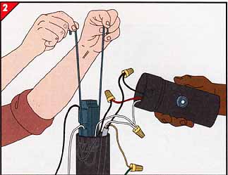
Nearly any outlet that has two cables entering it contains a suitable power source—a hot supply wire uninterrupted by a switch. A junction box, however, may have only switch-controlled wires. To check, cut off all power at the service panel, then unscrew the wire cap from a connection in the junction box that has at least one black wire. Use a voltage tester to be sure power is off: Hold one probe against the bare wires and the other against a bare copper ground wire. The tester light should not glow. Hold the probes in the same position while a helper re stores power; if the light now glows, the wire is hot and can serve as a power source.
Protective Armor: Conduit—the electrician’s term for pipe—is a feature of virtually any 120-volt outdoor circuit. It must always be used to protect wires aboveground and is often used underground as well. Rigid conduit is a popular choice because the required burial depth is only 6 inches.
TOOLS:
- Voltage tester
- Hacksaw
- Metal file
- Pipe wrenches (10”)
- Conduit bender
- Adjustable wrench (12”) or open-end wrench (1 1/8”)
- Electric drill with masonry and spade bits and an extender
- Cold chisel
- Ball-peen hammer
- Star drill
- Putty knife
- Multipurpose electrician’s pliers
- Edging tool
MATERIALS:
- Cable connector
- Wire caps
- Box extenders
- Metal conduit
- Conduit fittings
- Conduit straps
- Weatherproof caulking
- Mortar
- Green insulated wire
- Splice caps and insulators
SAFETY TIPS:
Wear goggles to protect your eyes when hammering a cold chisel or star drill against concrete or masonry.

A security lighting system. Although specific requirements
can vary widely, the principles of the security light system illustrated
at right can be applied to almost any house. In this situation, a mercury-vapor
lamppost fixture illuminates the door, the windows on both sides of the entrance, and most of the front yard. The shadow cast over the garage door and driveway
by the retaining wall is eliminated by an incandescent floodlight aimed down
from above. Light from a single mercury-vapor utility fixture bathes both
the right side and the back of the house. A streetlight suffices for the
left side.

Yard-brightening lamps. The lamppost fixture at far
left has been adapted for mercury-vapor security lighting with two additions:
a ballast hanging inside the post and a section of tubing that houses an
electric-eye switch. The lamp illuminates a circle about 30 feet in diameter.
The 175-watt mercury-vapor utility fixture at near left has a built-in ballast and electric eye. When mounted high above the ground, it lights a circle
about 80 feet wide.

Sensor-controlled floodlights. The motion sensor mounted
beneath the fixture at near right and the wand-type electric eye on top of
the fixture at far right switch on incandescent spotlights automatically.
Both lights can be aimed to shine where needed most. They cast narrow cones
of light with a base diameter roughly equal to the height of the fixture
above the ground.
Working with Conduit

An array of fittings. At left are the most common fittings for rigid, or heavy-wall, metal conduit. Elbows, for turning corners,
have curved access plates that must be weatherproofed with caulking cord.
Offsets help jog conduit past small obstacles. Screw-on plastic bushings
keep insulation from chafing against conduit edges. The continuous-feed,
or C, body provides access to wires in conduit with many turns, while a T
body branches a circuit. Both fit tings come with weatherproof gaskets.
Buried rigid conduit must be laid at least 6 inches below the surface. If you bury an elbow C body, or T body, you must mark its location permanently with a fixture or a short stake.

Couplings and connectors. Couplings join two lengths
of conduit, and connectors usually serve to fasten conduit to various pieces
of hardware. Some used with heavy-wall conduit are shown at left. Threaded
couplings, tightened with a pair of 10-inch pipe wrenches, join uncut conduit
ends. Threadless couplings join pieces of cut conduit that no longer have
threaded ends. After inserting conduit into the coupling, use a 12-inch-long
adjustable wrench or a 1 open-end wrench to tighten the nut until the conduit
is secure. Threadless connectors join cut conduit to an outlet box, a threaded
coupling, or a conduit fitting. Because threadless couplings and connectors
are tightened by turning nuts rather than an entire section of conduit, they
are also used to join large, unwieldy conduit assemblies.

Bending metal conduit.
• Cut conduit to measure with a hacksaw and de-burr the edges with a metal file.
• Pencil a mark on the conduit where the bend is to begin.
• Insert the conduit into the bender and align the mark with the arrow on the side of the tool.
• Step on the rocker tread and pull on the handle (above). To get proper lever age, you may need to brace the opposite end of the conduit against a wall.
• Some benders are equipped with 45- and 90-degree levels to indicate when the conduit is bent to the desired angle. Otherwise, use the following rules: For a 45-degree bend, pull the handle until it's vertical; for a 90-degree bend, continue pulling until the handle is halfway to the ground. Either way, the bend will be about 6 inches across (inset).
For an S bend, begin as described above. To make the next part of the curve, turn the bender over so that its handle rests on the ground. Position the conduit in the bender and bend it downward by hand, using a helper if necessary.
Running a Cable for on Outside Light

Tapping power.
• Turn off power at the service panel.
• Remove a circular knockout from the box and install a cable connector in the knockout hole.
• Thread a new cable into the box and tighten the connector clamp onto the cable.
• Using wire caps large enough to accommodate the extra wire, make the connections—black wire to black, white to white, and the bare copper ground wire to the bare or green wires. Replace the box cover.
• Run the new cable to the planned location of the outdoor fixture.
CAUTION: Never work on a live circuit. When working at a junction box, switch off all power to the house, because wires from more than one circuit may run through the box. and be fore you begin work, check all wires with a voltage tester to make sure power is off.
Tapping an Existing Fixture

1. Modifying the outlet box. A fitting called a box
extender provides the room needed to make wiring connections and attach conduit.
• Turn off the power. Remove the light fixture (or receptacle) from the box. Undo the electrical connections.
• Screw one end of a short piece of conduit called a nipple into an elbow and the other end into a conduit hole in the box extender. Temporarily screw the fixture, gasket, cover plate, and extender to the outlet box.
• Clamp the nipple to the wall with a conduit strap and caulk any gap between the box extender and the house.
• Later, remove the fixture to fish cable into the ex tender and to make the necessary wire connections, then screw the fixture permanently in place.

2. Assembling conduit along the house.
• Run conduit from the el bow at the box extender to the bottom course of siding. Strap the conduit to the wall.
• With a conduit bender, shape a conduit section to curve around the bottom of the siding and rest on the floor of the trench. Check the fit of this piece after making each bend.
• With a threadless coupling, link the contoured section to the conduit strapped to the house.
Installing a Box in Concrete Block

1. Making an opening. You can recess an indoor box
with adjustable ears into a block wall.
• Hold the box against the center of a block and outline it with tape. If seams between blocks have been stuccoed over, bore a test hole with a masonry bit in an electric drill to find a hollow. Insert a bent wire in the hole, feel around for the sides of the hollow, and mark a box opening between them.
• Use a 3/8-inch electric drill with a 1/2-inch masonry bit to bore several holes inside the tape. Finish the opening with a cold chisel and ball peen hammer, making the hole ¼-inch wider and longer than the box.
• Attach the masonry bit to an extender and drill a single hole through the far side of the block. Hammer a star drill to enlarge the hole for cable.

2. Mortaring the box in place.
• Insert screws loosely into the box’s fixture-mounting screw holes to keep out mortar.
• Adjust the ears so that the edge of the box extends about inch from the wall; this slight extension allows the cover-plate gasket to form a tight seal around the box.
• Clamp the cable to the box.
• Slide the box into place and press mortar into the gap between the box and hole with a putty knife. Mortar must completely fill the gap to anchor the box securely and to weatherproof the installation.
• When the mortar has dried, remove the screws from the mounting tabs.
An Exit from a Basement or Crawlspace

1. Drilling the exit hole. For underground-feeder,
or UF, cable, install an L-shaped connector known as an LB fitting; individual
wires require an outlet box and a cover without openings.
• Locate an exit point above the sill plate where joists will not hinder work and where an LB fitting or outlet box will not overlap a siding joint.
• Drill a 1/8-inch test hole through the siding and floor framing behind it. If the exit point is satisfactory, enlarge the hole with a 7/8-inch spade bit.
In concrete block, bore through the center of a block in the second course below the sill plate. Enlarge the test hole by hammering a 7/8-inch star drill, rotating the tool an eighth-turn after each tap. Make an identical hole in the other side of the block.

2. Installing the fitting.
• Select a nipple long enough to reach through the wall and screw it to an LB fitting or the back of an outlet box.
• Temporarily insert the nipple into the hole, and bend conduit to run from the fitting into the conduit’s trench.
• Withdraw the fitting from the wall, screw it onto the conduit, and push the nipple back through the wall.
• Strap the conduit to the side of the house. If an outlet box is used, screw the box to the wall and caulk around it; for an LB fitting, caulk around the nipple where it enters the house.
Recessing a Light in a Stairway Wall

Securing the fixture.
• With a cold chisel, chip out a brick and the surrounding mortar.
• Bore a 7/8-inch hole through the wall and into the conduit trench with a star drill.
• Assemble the fixture as necessary. In the back, screw a nipple long enough to extend into the trench. Push the fixture into the recess.
• If there is space around the front of the fixture, hammer in wood shims at the top and bottom. Pack mortar around the fixture and the nipple where it protrudes from the back of the wall.
• After the mortar dries, screw an out door box to the protruding nipple and thread the fixture leads through the nipple and into the box.
• Install a light bulb and mount the fixture cover plate.
Mounting a Fixture in an Eave

1. Installing a weatherproof outlet box.
• Drill a 1-inch exit hole in the house exterior at the location of the new fixture—in this ex ample, in the fascia. Tap an indoor circuit and run cable through the exit hole.
• Outside the house, slide the four pieces of a weatherproof cable connector (inset) over the end of the cable and tighten the connector.
Hold the connector with pliers and screw an outdoor outlet box onto it.
• Set the connector in the hole and screw the box in place through the hinged mounting tabs.

2. Wiring the fixture.
• Screw together the threaded nipple and the strap that come with the mercury-vapor lamp fixture, and fasten the strap to the tabs of the outlet box with the screws provided.
• Connect one grounding jumper—a 6-inch length of green insulated wire—to the green grounding screw on the back of the fixture, and another to the grounding screw of the outdoor box.
• As a helper holds the fixture, use wire caps to connect the jumpers to the bare wire of the cable, and make the connections between the other fixture and cable wires—white to white and black to black.

3. Mounting the lamp.
• Slide the metal hood of the fixture over the nipple and screw a cap nut onto the nipple until the hood gasket is tight against the outlet box.
• Fit the doughnut-shaped plastic lens to the fixture with the clips provided by the manufacturer, then screw the mercury-vapor bulb into its socket.
• To test the lamp, cover the electric eye on top of the hood with black tape and restore power. The lamp should turn on in about 1 minute.
Adapting a Yard Light to a Mercury-Vapor Bulb

1. Connecting the ballast and electric eye.
• Turn the power off. Remove the incandescent fixture from the top of the lamppost and disconnect its wires.
• Have a helper hold a ballast matching the wattage of the bulb and an electric eye housed in a length of lamppost tubing while you connect their wires to the cable inside the post. Using wire caps, join the white wires of the cable and the electric eye to the ballast wire marked COMMON, the black cable wire to the black wire of the electric eye, and the red wire of the electric eye to the ballast wire marked 120 VOLTS or LINE. don't , at this point, connect the wires marked LAMP and LAMP COMMON.
• Extend the bare ground wire of the cable with a 1-foot length of green insulated wire.
2. Mounting the ballast and eye.
• Set the ballast, with the lamp and lamp common wires up, into the U-shaped strap provided by the manufacturer, lower the strap into the lamppost, and hook the tabs at the ends of the strap over the outside of the post.
• Thread the lamp, lamp common, and cable ground wires through the tubing that houses the electric eye. Fit the bottom of the tubing over the top of the lamppost and , using holes in the tubing as a template, drill holes in the post.
• Fasten the tubing with the self-tapping screws provided by the manufacturer.

3. Wiring the lamp fixture.
• Have a helper hold the fixture while you make connections with wire caps: the lamp’s green or bare ground wire to the green cable wire, the lamp’s white wire to the ballast wire marked LAMP COMMON, and the lamp’s black wire to the ballast wire marked LAMP.
• Slide the fixture over the top of the electric-eye tubing and use the holes in the bottom of the fixture as a tem plate to drill matching holes in the tubing.
• Screw the lamp to the tubing.
Install a mercury-vapor bulb that matches the wattage of the ballast and has a “medium base,” designed to fit a standard lamp socket. Test the lamp fixture as explained in Step 3.
An Incandescent Flood Lamp

1. Installing the box and electric eye.
• Thread the wires of a type electric-eye switch through the hole at one end of an out door outlet, screw the switch into the box, and tighten the star nut.
• Tap an indoor circuit and mount the outlet box as described above. Then aim the wand of the electric eye toward the sky and away from streetlights and other sources of light.

2. Wiring the lamp holder.
• Attach a weatherproof lamp holder in the threaded opening in the outlet-box cover and tighten the star nut.
• Slide the gasket over the lamp-holder wires and connect the wires with wire caps. Connect the bare ground wire of the supply cable to the grounding screw of the outlet box, join all white wires, connect the black cable wire to the black wire from the electric eye, and connect the eye’s red wire to the lamp holder’s black wire.
• Screw the cover plate to the outlet box, making sure that the gasket seats snugly. Install a weatherproof 75-watt in candescent floodlight, aim the lamp, and test it (Step 3).
Low-Voltage Lighting

1. Installing the transformer.
• Mount the wall bracket supplied with the transformer at least 12 inches above the ground on a wall or post, and within 6 feet of a receptacle; then push the transformer onto the bracket.
• Place the fixtures and string the low- voltage cable from the transformer, leaving enough slack to follow walk ways and flower beds. Leave 12 inches of additional slack at each fixture.

2. Using splice caps.
• For a fixture with wire leads, cut the cable at the locations you have chosen, strip inch of insulation from each cable and fixture wire, and twist each fixture wire to the wires from each end of the cut cable. Crimp a splice cap over each three-wire connection with multi purpose electrician’s pliers.
• Partially fill an insulator with silicone caulking compound and slip it over the splice cap, making sure that the cap is embedded in the compound.

3. Hiding the cable underground.
• Push an edging tool into the ground with one foot, rocking it back and forth to exert a down ward and sideward pressure. Overlapping strokes will cut a narrow slit.
• Tuck the cable into the slit and step along the top to press the turf back together.
Previous: A
Boundary of Chain-Link Fence
Next: Strengthening Vulnerable Doorways